Monday 31 October 2016

Micro Operation

Take one classic Operation game and connect a BBC micro:bit to it, what could be more fun.  Having seen a similar project I thought I would have a go myself, so I had a quick browse on eBay and found one cheap. 


A few days later the game turned up and it appeared to be in good condition.  I removed the existing black box containing the electronics, the batteries had corroded but luckily only the battery connections had been damaged. I took everything out and connected some new wires to the tweezers and connection to the metal plate.  I also replaced the existing LED.


Existing electronics, somewhat crusty.


Existing electronics removed and new wires connected.


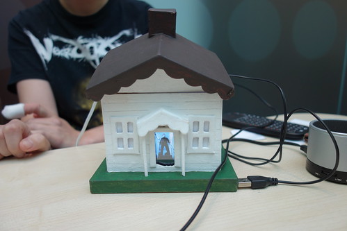
I connected the new wires up to the GPIO pins on the BBC micro:bit and tried out the awesome code written by David Whale.  I used my new Proto-pic exhi:bit Prototyping system for micro:bit but the Kitronik prototyping system would work just as well.  The game was fun to play and had some awesome animations. After 3 operations, if you are successful in the operation time limit, the man jumps out of the bed and walks away.


BBC micro:bit Edge Connector 
Operation game connections
P0 pin
Tweezers, active high
P1 pin
Nose LED via series resistor
P2 pin
Speaker, other pin to GND
+3V
Internal metal plate


You will need:
1 x Operation game
1 x BBC Micro:bit
1 x 5mm Red LED
1 x Suitable resistor for your LED (I used a 47)
Connecting wires
1 x speaker or piezo

The code was written by David Whale and can be found below.

A simple version of the game can be found  here  

Full version of the game can be found  here

Teleporting Ducks

The excellent Python MU editor makes it so easy to get BBC micro:bits talking to each other using simple radio data communication. No magic required, just physics.

After attending a brilliant talk / demo about the MU editor by Nicholas Tollervey, I came away feeling inspired.  I thought I would have a go myself and in no time I had 2 microbits sending data to each other wirelessly.   

I wrote some simple code based on an example by Nicholas Tollervey. First to send an image when pressing button ‘A’ between micro:bits.

  1. from microbit import display, button_a, Image
  2. import radio
  3. radio.on()
  4. while True:
  5.     message = radio.receive()
  6.     if message:
  7.         display.show(Image.DUCK)
  8.     if button_a.was_pressed():
  9.         display.clear()
  10.         radio.send("hello")


Next I thought it would be fun to add some neopixels. When button A is pressed the neopixels show red then amber on the sending microbit and green plus the image on the receiving microbit.

  1. from microbit import *
  2. import radio
  3. import neopixel
  4. np = neopixel.NeoPixel(pin0, 1)
  5. green = (0, 255, 0)
  6. red = (255, 0, 0)
  7. orange = (255, 153, 0)
  8. radio.on()
  9. while True:
  10.     # Read any incoming messages.
  11.     message = radio.receive()
  12.     if message:
  13.         np[0] = (green)
  14.         np.show()
  15.         display.show(Image.DUCK)
  16.         sleep(3000)
  17.         np.clear()
  18.     # Button A sends a "flash" message.
  19.     if button_a.was_pressed():
  20.         np [0] = (red)
  21.         np.show()
  22.         sleep(1000)
  23.         np [0] = (orange)
  24.         np.show()
  25.         sleep(1000)
  26.         np.clear()
  27.         display.clear()
  28.         radio.send("hello")


To connect the neopixels you’ll need to attach them to the micro:bit as below.


You will need:

2 x  BBC micro:bits
2 x Neopixels ( I used Crumble Sparkles )
6 x Crocodile leads

The code is available here.

Sunday 16 October 2016

12th Egham Raspberry Jam

On Sunday 16th October I travelled down Egham to attend the 12th Egham Raspberry Jam, it's my first time I have attended this particular jam.  It was held at the Gartner UK HQ offices, which was easy to find and had plenty of parking. There were plenty of cool show and tell projects to look at, but no workshops or talks.  

I took a couple of BBC micro:bit projects and my Raspberry Pi trick or treat detector project along. I spent most of my time talking to people about my projects, however I did manage to have a look at the other projects on show.


My Show n Tell projects.

IMAG0475

Nevil Hunt had several nice BBC micro:bit projects on display.

DSC02033

A nice haunted house.

DSC02037

Raspberry Pi machine which dispensed pancakes complete with jam.

DSC02049


Acorn electron with Raspberry Pi and Arduino inside.

DSC02055

Matt Sendorek's Raspberry Pi controlled Maplin robot arm.

DSC02057

Carl Monk's Breakout Clone.

DSC02061


Some more pictures can be found on my Flickr page.

Saturday 8 October 2016

Trick or Treat Detector

Detect those pesky kids before they get to the front door. Put it outside to spook the Trick-or Treaters as they walk up to your door. This project is motion activated using a PIR sensor, upon activating the Owl and some cheap LED string lights turn on.

Step 1.  Prototyping
I built the circuit on a breadboard to test the idea. I used the PIR sensor and breadboard from the brilliant CamJam EduKit 2.  I used transistors to drive the LED’s as the Raspberry Pi GPIO pins cannot supply a lot of current. The code was written in Python using the great GPIO Zero API.  I set the Python script to load on start-up.


Breadboard layout


GPIO Connections

GPIO 4 -  PIR sensor
GPIO 5 - Owl via driver transistor
GPIO 6 - Bat lights  via driver transistor
GPIO 12 - Hand lights via driver transistor
GPIO 17 - Shutdown switch


Step 2.  Transferring the circuit onto a PCB

The circuit worked well so I decided to transfer the breadboard prototype onto a more permanent Adafruit Perma-Proto HAT.   


Step 3. Building into an enclosure

While looking for suitable enclosures in Poundland I came across a nice plastic pot full of Halloween sweets, having removed the sweets to eat later.  I set about cutting some holes in the pot for the PIR sensor and 3.5mm mono jacks.   I connected all of the cables and checked that it worked. 


Parts List:
1 x  Raspberry Pi board, any model will work
3 x  NPN Transistors
3 x 10KΩ Resistors
3 x Suitable resistors for the LED’s ( I used 22Ω resistors)
1 x PIR Infrared Motion Sensor (HC-SR501)
1 x PCB tactile switch
3 x 2 way Molex KK type 2.54mm headers and housing
1 x 3 way Molex KK type 2.54mm headers and 2 housings

Some cheap Halloween lights from Poundland

Complete code listing:


  1. from gpiozero import *
  2. from subprocess import check_call
  3. from signal import pause
  4. import time
  5. pir = MotionSensor(4)
  6. owl = LED(5)
  7. bat = LED(6)
  8. hand = LED(12)
  9. owl.off()
  10. bat.off()
  11. hand.off()
  12. print("waiting for pir to settle")
  13. pir.wait_for_no_motion()
  14. while True:
  15.     print("ready")
  16.     pir.wait_for_motion()
  17.     print("motion detected")
  18.     owl.on()
  19.     bat.blink()
  20.     hand.blink(2,2)
  21.     time.sleep(30)
  22.     owl.off()
  23.     bat.off()
  24.     hand.off()
  25.     def shutdown():
  26.         check_call(['sudo', 'poweroff'])
  27.     shutdown_btn = Button(17, hold_time=2)
  28.     shutdown_btn.when_held = shutdown