Monday 22 October 2018

Crow-O-Matic


While pursuing the Halloween tat in Poundland recently, I saw an empty bird cage.   This gave me an idea, could I reuse the two creepy Halloween crow’s I brought and modified last year.

I came up with the idea of putting them in the bird cage and making them move, using servos.  So I duly purchased an excellent Picon Zero board and some servos from 4tronix. When the board arrived I did some testing to see if my idea worked.

The Picon Zero board and servos are available from 4tronix, links below


Step  1.


I temporarily Blu tacked the crows on top of the servos and tried the example servotest Python code that was included with the PiCon Zero board library to see how well they moved,  well it worked it treat.

Step 2.


I added a PIR sensor so that when it detected movement it would trigger the movement of the crows, turn the on the glowing red eyes and annoying crowing noises when you pass in front of the crows.

Step 3.


I finalised the Python code and then set about putting it into the birdcage I had brought.   After much glueing and cutting of black card I had a finished project.    

The completed project 


Complete Code Listing


  1. import piconzero as pz, time
  2. def sensor_activated():
  3.     return pz.readInput(0)
  4.    
  5. def initialise():
  6.     # Setup
  7.     pz.init()
  8.     pz.setOutputConfig(0, 2)   # pin 0 servo output  
  9.     pz.setOutputConfig(1, 2)   # pin 1 servo output
  10.     pz.setOutputConfig(2, 0)   # pin 2 digital output
  11.     pz.setInputConfig(0, 0)    # pin 0 digital input
  12. def deactivate_defences():   # Centre servos and turn off relay
  13.     print ("Crows on standby")
  14.     pz.setOutput(0, 90)
  15.     pz.setOutput(1, 90)
  16.     pz.setOutput(2, 0)
  17. # main loop
  18. try:
  19.     initialise()
  20.     while True:
  21.         deactivate_defences()
  22.         time.sleep(5) # Avoid rapid retriggering
  23.         while not sensor_activated():
  24.             time.sleep(0.2)
  25.             print("Motion detected")
  26.             pz.setOutput(2, 1)
  27.             pz.setOutput(0, 40)
  28.             pz.setOutput(1, 150)
  29.             time.sleep(5)
  30.             pz.setOutput(0, 150)
  31.             pz.setOutput(1, 40)
  32.             time.sleep(5)
  33.             pz.setOutput(0, 90)
  34.             pz.setOutput(1, 90)
  35.             time.sleep(5)
  36. finally:
  37.     pz.cleanup()

Sunday 22 April 2018

BBC Micro Model B Repair and Restoration Project

I’ve always had a bit of a soft spot for the BBC Micro, having been introduced to the machine at school back in the late 80’s.  I decided to try and find myself an original Beeb, so off to eBay to look for a suitable candidate.

After some looking I found a suitable BBC Micro Model B, I duly purchased this for the princely sum of £50 plus shipping.  After a short wait, it duly arrived but I didn’t power the machine up as the power supplies have a nasty habit of letting out the magic smoke. In the mean time I had sourced a suitable RGB to Scart cable and a PSU repair replacement capacitor kit.  Both of these came from the excellent Retro Computer Shack.

My BBC Micro


Inside the BBC Micro, the previous owner had fitted a Watord Electronics Sideways ZIF Socket which allows you to change ROMs with the minimum effort.

Replacing the capacitors


WARNING!

Dangerous voltages reside inside the PSU, even when switched off and unplugged.   
Ensure that all the high voltage caps are safely discharged first!

YOU SHOULD READ THE WARNING LABEL


The first job was to remove the power supply from its case. This can be a little tricky as you need to remove a couple of earth bolts, push out the disk drive power connector and disconnect the mains power switch.

Power supply removed from the Beeb


Once the PSU had been wrangled out of its case, I set about replacing the 10nF (0.01µF) and 100nF (0.1µF) X class mains filter capacitors and a small 220µF electrolytic capacitor which sometimes causes intermittent power supply startup issues.  The modern replacement mains filter capacitors are X2 class.  

The RIFA branded capacitors are prone to failures, when the do fail they realise plumes of noxious smoke. 

Power supply extracted from its case


Existing RIFA capacitors, ticking time bombs 


New X2 mains filter capacitors fitted


Here's a shot of  the old RIFA capacitors showing those stress lines and hairline cracks that would eventually result in a failure.

With the capacitors replaced I re-assembled the power supply. I fitted it back into the BBC Micro and powered on, it passed the smoke test phew.  Alas the BBC Micro would not start up, It just emitted a continuous tone and there was no display on the screen.

Repairing the poorly BBC Micro


The fault I was getting could be caused by a faulty video processor chip but as I didn’t have one to hand,  I tried re-seating the chip and I also re-seated some of the other chips but this made no difference. Next step try checking the voltages, which were all correct but when I was probing the various +5V, -5V and 0V connectors on the main PCB, it suddenly sprang into life.

Hmm I thought it could be a dry joint so I removed the main PCB and checked for dry joints but couldn’t see any.  There are several power supply connection points on the main PCB, which are FASTON PCB Tab type connectors. I re-flowed all of these connections on the back of the main PCB.  Having done this, I re-assembled the machine and tried again. Success the machine started up correctly, I got the classic twin tone beep and was presented with the start screen prompt.


Finally I gave the case a good clean using hot soapy water to remove the years of ground in grime.


More repairs..

Having repaired my beeb, I thought I would try loading a game from cassette, well it would appear my beeb is deaf.  I tried loading a couple of games from tape but it doesn't appear to acknowledge with Searching. I've also tried to save but the cassette LED doesn't come on and there's no acknowledgement with Record then return message.


I tried the following:

1. Just playing a tape which appears to make all the correct noises
2. Changing the cassette lead
3. Swapping IC35 (LM324 Op Amp)
4. Reseating IC7 (Serial 2C199E-7 ULA) 

I have verified that the cassette motor LED and relay work by removing the serial ULA and connecting PIN 11 to +5v. 

Op Amp and Serial ULA locations


Faulty Serial ULA


So I went off in search of a replacement serial ULA,  I eventually managed to source one from a member of the Stardot forum, having fitted the replacement serial ULA my beeb now works correctly.
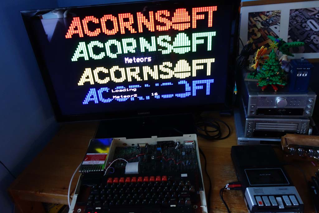
Success!


Sunday 25 March 2018

Building a awesome VIC20 controlled tank

Updated 05/04/18

I have recently been thinking about building a Commodore VIC20 controlled robot.  Some inspiration came from the classic 1980s Usborne How to Make Computer-Controlled Robots book [3] and the BBC Buggy[4].   


You will need:


How to build:

First I needed to laser cut the tank chassis.  I downloaded the DXF file and opened it in
Techsoft 2D Design (This is the CAD software we use with our laser cutter).  


Cutting out the parts from an 5mm perspex sheet on the laser cutter


Once the parts were cut out, I set about building the tank using the tank building resource instructions.  


Electronics:

Next I built the motor controller board using the supplied instructions.  The board was originally designed to use with a 18 pin PIC microcontroller, I used a programmed PICAXE 18M2 chip[1] to test that the inputs and outputs worked correctly. The board was functioning correctly so I set about building a suitable interface circuit.

I built a prototype circuit on a breadboard to test that I could interface the VIC 20 user port with the FAN8100N motor driver IC on the motor control board. I used a 74HCT244[2]. User port I/O numbers 0 to 3 are connected via the 74HCT244 to the forward and reverse inputs on the FAN8100N motor driver IC.

These tests worked so I went on to add a simple LED display to monitor the status of the user port and added some circuitry to interface the inputs from the existing motor controller board with the VIC 20 user port.  I then verified that the inputs worked correctly.  Now that the circuitry was working correctly I transferred the breadboard layout onto stripboard to make things more permanent.

I removed the existing PIC socket and soldered some Molex headers in place so I could connect the robot to my VIC20 via a 5 meter length of ribbon cable.  


I added some micro switches to the front of the tank and a line following board to the chassis.


Completed stripboard layout


Schematic


1 Input circuitry

Input signals from the motor controller PCB (at TTL logic 0 and 1) are applied to the inputs of the 74LS14 Schmitt trigger IC. This is an inverting Schmitt trigger, so that a logic 1 input will cause the associated output to go to logic 0.  The 1KΩ resistors pull the input down to 0V (logic 0) in the absence of input signals.   

A logic 0 out at the Schmitt trigger will cause the cathode of the appropriate LED in the quad opto-isolator IC to go low, so turning the LED on.  This turns on the associated photo-transistor in the opto-isolator and its emitter goes high (due to the p.d across the 1.2kΩ resistors). The logic levels at these emitters are connected directly to the user port PB4-7, which are configured as inputs.   The Schmitt input circuitry ensures precise triggering, whilst the use of opto-isolation obviates the possibility of damage to the microcomputer.

2 User port status LED 

User port signals PB0 -7 are feed through a 74LS540 Octal buffer and line driver IC.  The outputs of this IC are inverted so an logic 1 will turn the LED on in the 10 way light bar LED display.

3 Motor driver

User port signals PB0-3 are feed through a 74LS244 Octal buffers and line driver IC. The outputs of this IC are connected to the FAN8100N Motor driver IC on the existing motor controller PCB.


Mechanical assembly:


I started to assemble the chassis, once this was done I assembled the tracks.


Wiring:

Now the mechanical assembly is complete, I could start wiring things up.  Each motor has a + marking on it, so I made sure the red coloured wire was soldered to that terminal.


Coding:


With all the wiring in place, I tested motors to make sure they worked correctly.  I need to write some BASIC code to make the tank do something, I'll get onto that later.


Testing the sensors


This simple program makes the robot move forward until it hits something, then reverse and swivel right or left before setting off again.  I found this in the Usborne Practical Things To Do with a Microcomputer book.

10 POKE 37138,15
20 LET Y=37136
30 POKE Y,5
40 LET Z=PEEK(Y)AND16
50 IF Z<>0 THEN GOTO 70
60 GOTO 40
70 POKE Y,10
80 FOR I=1 TO 10
90 GOSUB 190
100 NEXT I
110 POKE Y,0
120 LET P=6
130 IF RND(1)>0.5 THEN LET P=9
140 POKE Y,P
150 FOR I=1 TO INT (RND(1)*20+10)
160 GOSUB 190
170 NEXT I
180 GOTO 30
190 FOR T=1 TO 100
200 NEXT T
210 RETURN

References


  1.  A PICAXE chip is a standard Microchip PIC microcontroller that has been pre-programmed with the PICAXE bootstrap firmware code. The bootstrap code enables the PICAXE microcontroller to be re-programmed 'in position' directly from a PC.
  2. This is an 8-bit buffer/line driver with 3-state output. The device can be used as two 4-bit buffers or one 8-bit buffer.
  3. These books are now freely available as PDFs from here.
  4. The BBC Buggy is an small robot designed to work with the BBC Microcomputer.