Showing posts with label Repairs. Show all posts

Sunday, 22 April 2018

BBC Micro Model B Repair and Restoration Project

I’ve always had a bit of a soft spot for the BBC Micro, having been introduced to the machine at school back in the late 80’s.  I decided to try and find myself an original Beeb, so off to eBay to look for a suitable candidate.

After some looking I found a suitable BBC Micro Model B, I duly purchased this for the princely sum of £50 plus shipping.  After a short wait, it duly arrived but I didn’t power the machine up as the power supplies have a nasty habit of letting out the magic smoke. In the mean time I had sourced a suitable RGB to Scart cable and a PSU repair replacement capacitor kit.  Both of these came from the excellent Retro Computer Shack.

My BBC Micro


Inside the BBC Micro, the previous owner had fitted a Watord Electronics Sideways ZIF Socket which allows you to change ROMs with the minimum effort.

Replacing the capacitors


WARNING!

Dangerous voltages reside inside the PSU, even when switched off and unplugged.   
Ensure that all the high voltage caps are safely discharged first!

YOU SHOULD READ THE WARNING LABEL


The first job was to remove the power supply from its case. This can be a little tricky as you need to remove a couple of earth bolts, push out the disk drive power connector and disconnect the mains power switch.

Power supply removed from the Beeb


Once the PSU had been wrangled out of its case, I set about replacing the 10nF (0.01µF) and 100nF (0.1µF) X class mains filter capacitors and a small 220µF electrolytic capacitor which sometimes causes intermittent power supply startup issues.  The modern replacement mains filter capacitors are X2 class.  

The RIFA branded capacitors are prone to failures, when the do fail they realise plumes of noxious smoke. 

Power supply extracted from its case


Existing RIFA capacitors, ticking time bombs 


New X2 mains filter capacitors fitted


Here's a shot of  the old RIFA capacitors showing those stress lines and hairline cracks that would eventually result in a failure.

With the capacitors replaced I re-assembled the power supply. I fitted it back into the BBC Micro and powered on, it passed the smoke test phew.  Alas the BBC Micro would not start up, It just emitted a continuous tone and there was no display on the screen.

Repairing the poorly BBC Micro


The fault I was getting could be caused by a faulty video processor chip but as I didn’t have one to hand,  I tried re-seating the chip and I also re-seated some of the other chips but this made no difference. Next step try checking the voltages, which were all correct but when I was probing the various +5V, -5V and 0V connectors on the main PCB, it suddenly sprang into life.

Hmm I thought it could be a dry joint so I removed the main PCB and checked for dry joints but couldn’t see any.  There are several power supply connection points on the main PCB, which are FASTON PCB Tab type connectors. I re-flowed all of these connections on the back of the main PCB.  Having done this, I re-assembled the machine and tried again. Success the machine started up correctly, I got the classic twin tone beep and was presented with the start screen prompt.


Finally I gave the case a good clean using hot soapy water to remove the years of ground in grime.


More repairs..

Having repaired my beeb, I thought I would try loading a game from cassette, well it would appear my beeb is deaf.  I tried loading a couple of games from tape but it doesn't appear to acknowledge with Searching. I've also tried to save but the cassette LED doesn't come on and there's no acknowledgement with Record then return message.


I tried the following:

1. Just playing a tape which appears to make all the correct noises
2. Changing the cassette lead
3. Swapping IC35 (LM324 Op Amp)
4. Reseating IC7 (Serial 2C199E-7 ULA) 

I have verified that the cassette motor LED and relay work by removing the serial ULA and connecting PIN 11 to +5v. 

Op Amp and Serial ULA locations


Faulty Serial ULA


So I went off in search of a replacement serial ULA,  I eventually managed to source one from a member of the Stardot forum, having fitted the replacement serial ULA my beeb now works correctly.
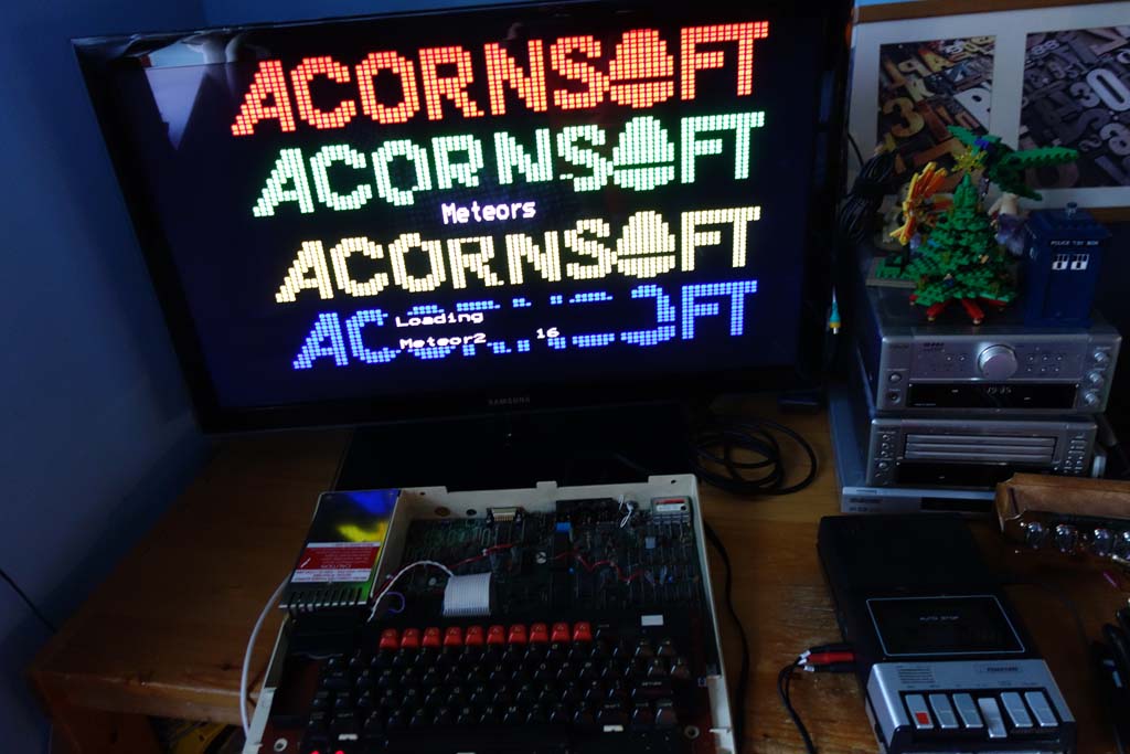
Success!


Tuesday, 2 May 2017

Commodore 1541 Disk Drive Repair

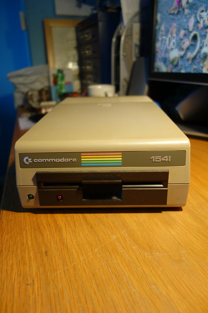
I recently acquired a classic Commodore 1541 disk drive.  It was in good condition, powered on and came with the original transit card (sometimes called a ”head vibration protector”).   


DSC02640

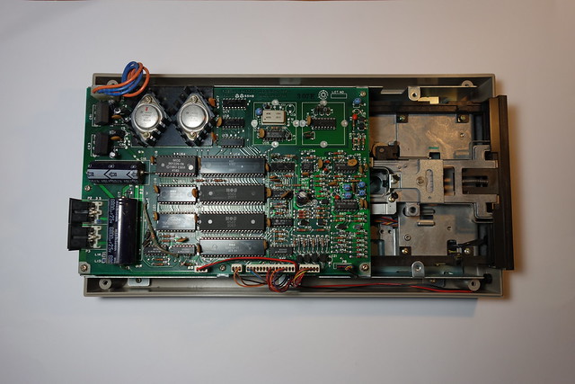
When it arrived I opened it up to have a peek inside. There is a large PCB which contains a MOS 6502 microprocessor, 2x MOS 6522 Versatile Interface Adapter (VIA) IC’s, rom, ram and various glue logic. I gave it a quick clean and powered the drive on, no magic smoke escaped. The drive powered up normally but the spindle motor didn’t appear to be running hmmmm.

DSC02641


Luckily there is plenty of technical information about these drives available on the web. Here are a couple of useful websites.

Bo Zimmerman's Commodore 1541 disk drive information

Ray Carlsen's Commodore 1541 disk drive repair information

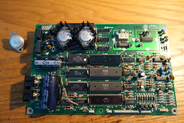
I started checking voltages, the +5v supply was ok but the +12v supply was missing. This could be caused by an overload due to a shorted tantalum capacitor (C15) which sits across the +12V rail. I replaced the capacitor but this made no difference, it would appear that the +12v regulator (LM340KC-12) was dead.

These voltage regulators come in a TO-3 style package but I didn’t have any of these in my component stocks, so I had a quick hunt on eBay for some replacements.  A few days later the voltage regulators turned up so I set about replacing the faulty one. After I fitted the new voltage regulator I checked the voltage rails, both the +5v and +12v were now present.  

I powered the drive on, the green LED came on and stayed on, the red activity LED came on and the spindle motor ran for about two seconds then the red LED went out and the spindle motor stopped.  Good news I could now test the drive.


DSC03173


Next step testing the drive:

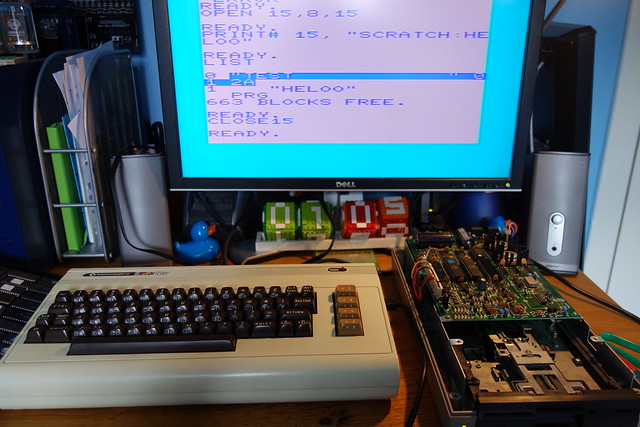
I hooked up the disk drive to my VIC20 and gave it a whirl, well that proved to be fruitless.  I tried to format a disk which started well, the red activity LED came on, the drive spindle motor was spinning and the head started to move across the disk. The format failed as the head stopped moving across the disk, the red activity LED started to flash (which indicates an error) but there were no error messages on the screen.   

Format failures can be caused by a write protect (disk tab on), drive door open, bad disk, bad or clogged head, or bad chips in the drive.  I tried cleaning the head with some alcohol and a cotton tip and then tried again.  Well that didn’t work, so I took a punt and swapped out the one of the  6522 VIA chips (UC2) which deals with the motor control logic.   Success the drive would now format a disk and read OK.

DSC03198


Sunday, 26 February 2017

Telequipment D65

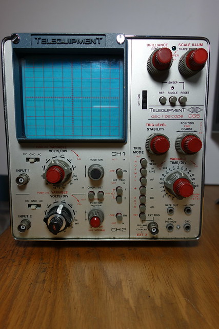
Some time ago I acquired an old 1976 vintage Telequipment D65 - 15MHz, all solid state dual-trace scope.  Unfortunately it had a couple of faults which is why it was being thrown away.

Telequipment D65

The scope basically worked but.
  1. It wouldn't turn on as the scale illumination / power switch knob was cracked and therefore kept slipping
  2. The trigger was intermittent, when powered on the triggered sweep may decide to a) start halfway across the screen, b) in the correct position and then fade or c) work as advertised.
Well the first thing I did was fix the broken knob, nothing a bit of superglue didn’t solve. This was only a temporary fix until I obtained a replacement second hand knob.  Now I could move onto fixing the annoying intermittent trigger fault. 

After a bit of digging around on the net I stumbled across this post on the UK Vintage Radio Repair and Restoration forum. Somebody else was having the same issue which could be fixed by tapping the trigger knob or the side of the case for that matter. 

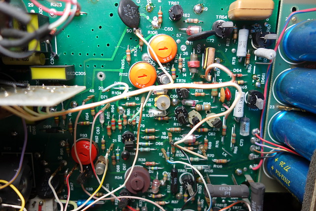
Trigger, Timebase X amp & blanking PCB
Troublesome PCB


The fault was on the trigger, time base x-amp and blanking PCB.  It would seem that these scopes use doubled sided PCB's with naff though hole links which go bad with age. I re-flowed the solder on all the little links and this fixed the problem. 

Overall I'm pleased with this little scope which weighs 11.5Kg, it has made a  great addition to the workshop.  I should recap the power supply board at some stage.

Some more pictures of this scope can be found on my Flickr page.

Tuesday, 23 August 2016

Marconi TF 2411 Nixie Counter Repair


Well I seemed to have inherited another Nixie counter.  This one is made by Marconi Instruments and is 70’s vintage.  The TF 2411 is a 50MHz counter which offers a wide range of functions, has three input channels and uses a mixture of DTL (Diode Transistor Logic) / TTL (Transistor Transistor Logic) integrated circuits.

This counter uses a non-standard XLR-LNE three-pin mains connector, so the first challenge was to try and obtain the correct mating connector.  After a bit of searching around I managed to obtain a suitable connector from a fellow UKVRRR forum member.   Having made up a new mains lead and suspicious XLR-LNE plug, I gingerly powered the unit on. It passed the smoke test, phew. 


XLR-LNE Connectors


I checked all of the voltage supply rails which were ok.  The display was incomplete and according the fault finding chart in the manual, it suggested a faulty Nixie tube.  I found that five of seven Nixie tubes were cracked and therefore rendered useless,  I had a quick look on eBay to find some replacement ZM1162 tubes.   


Dead Nixie tubes,   the cracks are outlined in red.


With the replacement Nixie tubes fitted, I proceeded to carry out the self-check as outlined in the manual, well that proved to be fruitless as the readout just displayed zeros.  I suspected the 10MHz frequency standard wasn't running.  So back to checking voltage levels at different points, I found that the +20v supply wasn’t present at pin 1 of the frequency standard unit. I followed the mass of cables to find where the wire went and discovered that it had broken at a pin connection on the amplifier PCB, re-soldering this wire restored the supply to the frequency standard.

I could now continue with the self-test, I switched through all time base positions but 1 – 4 just displayed zeros.  Hmmm well time to dig out the old oscilloscope and check the time base decades which are good old 7490N decade counters.  I could see the signal being passed from one decade counter to the next on the time base positions 5 – 8 but the signal wasn’t getting to the lower group of time base decades.  It goes through a Ferranti ZN224 (Quad 2 Input NOR gate) chip, I was probing around this chip and one of the outputs appears to be dead.  Therefore the 10MHz signal wasn’t able to get to the lower group of decade counters.


Below is a section of the Logic board schematic.

Dead logic chip outlined in red.


These chips are long obsolete but I did manage to a find some ZN346 (Quad 2 Input NOR gate) IC's on eBay and these according to an old data book are the same as the ZN224 but slightly slower, though I’m not sure if the pin outs are the same.  

Overall I'm very happy with the unit, it is beautifully made and works mostly. I may one day replace the dead logic chip but for the time being it has been consigned to the loft of plenty.

Some more pictures can be found here 

Update 26/08/2017

Having replaced the suspect ZN224 logic chip on the logic board, this seems to have cured the problem.  I switched the function switch to test and rotated the time base through it's positions, 1 - 4 now work.

Bad DTL logic chip has been replaced.


One bad chip.


Finally I checked my counter with my 10MHz OCXO module and all is good. 


Wednesday, 10 August 2016

Thurlby LA160 Logic Analyser

I recently acquired a Thurlby LA160B Logic Analyser. My unit is RS branded and was made some time during the late 80’s. It has 16 data channels and runs at 20 MHz, with various clock and trigger inputs.  My unit came with a data pod, which is a simple buffer. 

Data pod


My unit powers up then LA160B 35 is displayed, which tells me it is a LA-160B and the rom version is 35. Soon afterwards it says ready.  I checked the keypad which responds to the keypresses correctly.


Upon opening the unit up, I noticed that the NiCad battery has started to leak but not badly as there is no damage to the PCB or surrounding components.  I have ordered a replacement 2.4v 150mAh NiMH battery as NiCad batteries are no longer available.

Suspect NiCad battery


Update 11/08/16


I've removed the old battery, cleaned the PCB and fitted the new one. When I powered the unit back on it asked me to "set type", checking the label on the back will tell you which type you have.  I pressed the "B" button and bingo the type is now set.

Old battery removed


New battery installed


Some more pictures of my unit can be found here.
Thurlby LA160 Logic Analyser

I came across this site which has information about these logic analysers. http://sonicsheep.com/Electronics/2-Thurlby%20LA160.html

You can download a copy of the service manual from.

Tuesday, 19 July 2016

Marconi TF2438 Repair

I recently got an old 80’s vintage Marconi TF2438 Universal Counter Timer from a fellow forum member.  The unit looked very good and powered up but was sometimes intermittent.  The unit has an oven-stabilized 10 MHz crystal oscillator fitted which is a bit erratic when warming up but fine after 5 minutes or so.  The following faults still exist even though the previous owner had already done some fault finding.
  1.   It either says 0Hz    
  2.  Or reads high (approximately double the frequency, but not stable). The former, when it occasionally happens, is fixed by gentle "percussive maintenance", so that's clearly an intermittent connection.

After a bit of googling, I found out that a typical failure mode of these instruments made by Marconi Instruments at the time used double-sided PCBs with the two sides connected with what could only be called rivets. Over time, with thermal expansion and contraction, the solder on these rivets would crack and they became very unreliable. Some of the rivets had already been re-flowed.

Anyway I digress. I got the unit home, powered it up and connected the 10MHz standard output to channel B, it did measure the frequency but unfortunately it was up to its old tricks of reading high approx. double the frequency and despite some “percussive maintenance” I couldn’t get it to behave. I found a legible copy of the schematics, courtesy of UK Vintage Radio Repair and Restoration forum.  I guess it was time to check some voltages, there are four main d.c. supply rails,   +5.1V,  -5.1V, +12V and -12V.

The joy of fault finding


Function Board


Control Board


All of the supply rails were reading low approx.  +/- 4.0v.  I checked the rails pre-regulator and these seemed to be correct.  Inspired by a post on the UK Vintage Radio Repair and Restoration forum,  I started checking for shorts and faulty components on the bottom function PCB but I couldn't find anything wrong. I also checked components which share both +5.1V and +12V rails and removed the 10MHz oscillator but this made no difference.   Following some helpful suggestions, I ran some tests with and external power supply connected across D21 (a temperature-stabilised 6.2V Zener) and the + -/ 5.0v rails were ok.  Several suspect tantalum capacitors were changed, two pass transistors in the power supply were changed and an IN4148 diode.  Finally I replaced the IN4148 diode again and repaired a broken track/pad which had lifted when I had removed the original.  The supply rails then sprang back into life. 

These instruments have a nice feature which allows you to plug the top control PCB with display and switch board into the bottom function PCB via a second set of connections which improves access for servicing, therefore you don't need an extender card or any special cables.  

Having sorted the power supply issue my attention moved to the other annoying intermittent faults, which I suspected was due to a bad through-hole rivet somewhere on the control board.   I re-flowed every through-hole rivet I could find and cleaned the push-button switches with some switch cleaner.   Success, I tested the unit again and it now worked correctly.


Overall I’m very happy I managed to repair the annoying intermittent faults.  It is a beautiful instrument and well-made though I suspect that those through-hole rivets will come back to haunt me one day.

Sucess