Saturday, 8 October 2016

Trick or Treat Detector

Detect those pesky kids before they get to the front door. Put it outside to spook the Trick-or Treaters as they walk up to your door. This project is motion activated using a PIR sensor, upon activating the Owl and some cheap LED string lights turn on.

Step 1.  Prototyping
I built the circuit on a breadboard to test the idea. I used the PIR sensor and breadboard from the brilliant CamJam EduKit 2.  I used transistors to drive the LED’s as the Raspberry Pi GPIO pins cannot supply a lot of current. The code was written in Python using the great GPIO Zero API.  I set the Python script to load on start-up.
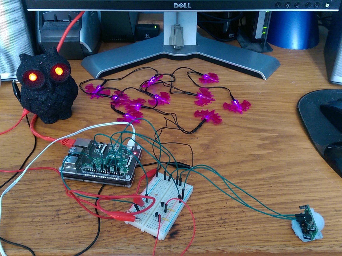


Breadboard layout


GPIO Connections

GPIO 4 -  PIR sensor
GPIO 5 - Owl via driver transistor
GPIO 6 - Bat lights  via driver transistor
GPIO 12 - Hand lights via driver transistor
GPIO 17 - Shutdown switch


Step 2.  Transferring the circuit onto a PCB

The circuit worked well so I decided to transfer the breadboard prototype onto a more permanent Adafruit Perma-Proto HAT.   


Step 3. Building into an enclosure

While looking for suitable enclosures in Poundland I came across a nice plastic pot full of Halloween sweets, having removed the sweets to eat later.  I set about cutting some holes in the pot for the PIR sensor and 3.5mm mono jacks.   I connected all of the cables and checked that it worked. 


Parts List:
1 x  Raspberry Pi board, any model will work
3 x  NPN Transistors
3 x 10KΩ Resistors
3 x Suitable resistors for the LED’s ( I used 22Ω resistors)
1 x PIR Infrared Motion Sensor (HC-SR501)
1 x PCB tactile switch
3 x 2 way Molex KK type 2.54mm headers and housing
1 x 3 way Molex KK type 2.54mm headers and 2 housings

Some cheap Halloween lights from Poundland

Complete code listing:


  1. from gpiozero import *
  2. from subprocess import check_call
  3. from signal import pause
  4. import time
  5. pir = MotionSensor(4)
  6. owl = LED(5)
  7. bat = LED(6)
  8. hand = LED(12)
  9. owl.off()
  10. bat.off()
  11. hand.off()
  12. print("waiting for pir to settle")
  13. pir.wait_for_no_motion()
  14. while True:
  15.     print("ready")
  16.     pir.wait_for_motion()
  17.     print("motion detected")
  18.     owl.on()
  19.     bat.blink()
  20.     hand.blink(2,2)
  21.     time.sleep(30)
  22.     owl.off()
  23.     bat.off()
  24.     hand.off()
  25.     def shutdown():
  26.         check_call(['sudo', 'poweroff'])
  27.     shutdown_btn = Button(17, hold_time=2)
  28.     shutdown_btn.when_held = shutdown

Saturday, 17 September 2016

CamJam September 2016

I traveled up to Cambridge on Saturday 17th September to attend another excellent CamJam.   I arrived early to help setup, this meant leaving home at an unreasonable hour for a Saturday.   I chatted to several people who had some interesting Show and Tell stuff and looked to see what was on offer in the Marketplace.  Rapid Electronics, PiBorg, 4tronix and Pimoroni were selling stuff, though I didn’t buy anything.

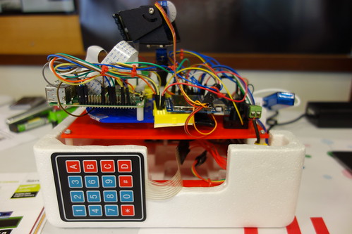
Spencer Organ had his excellent  Raspberry Pi/Arduino timelapse camera on display.  

DSC01884

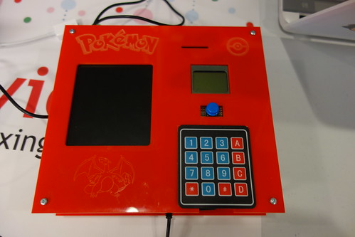
Philip Organ had his brilliant Raspberry Pi powered Pokemon Pokedex on display.  


DSC01885

Martin Mander had some cool projects on display.

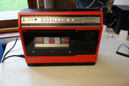
1981 Portable VCR Raspberry PI Media Centre
DSC01893

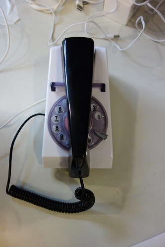
1970s Raspberry Pi Amazon AlexaPhone

Rabbit Pi
Rabbit Pi

The Raspberry Pi Batinator

David Saul had his Tempus Fugit WordClock, PI-LCD and PiMUxClock projects on display. 


DSC01900

Albert Hickey had his brilliant buttonflash game on display.


DSC01916

Phil Willis with Fritz.
DSC01917

Laura Trevail had several interesting IoT projects on display.

DSC01925

The Suttles had some interesting Raspberry Pi projects on display.


DSC01936

Workshops

I helped out with Exploring the real world with sensors workshop. The camjam edukit 2 was provided along with copies of the worksheets so people could try some of the examples.


Talks


I only attended a couple of talks, first up

Philip Organ spoke about the development of his Rasperry Pi/Arduino timelapse camera. Next up was Philip Organ who spoke about the building of his Pokemon Pokedex project.  

Finally Jim Darby spoke about using USB on-the-go on the Raspberry Pi from easy add-on to clustering.


Tuesday, 23 August 2016

Marconi TF 2411 Nixie Counter Repair


Well I seemed to have inherited another Nixie counter.  This one is made by Marconi Instruments and is 70’s vintage.  The TF 2411 is a 50MHz counter which offers a wide range of functions, has three input channels and uses a mixture of DTL (Diode Transistor Logic) / TTL (Transistor Transistor Logic) integrated circuits.

This counter uses a non-standard XLR-LNE three-pin mains connector, so the first challenge was to try and obtain the correct mating connector.  After a bit of searching around I managed to obtain a suitable connector from a fellow UKVRRR forum member.   Having made up a new mains lead and suspicious XLR-LNE plug, I gingerly powered the unit on. It passed the smoke test, phew. 


XLR-LNE Connectors


I checked all of the voltage supply rails which were ok.  The display was incomplete and according the fault finding chart in the manual, it suggested a faulty Nixie tube.  I found that five of seven Nixie tubes were cracked and therefore rendered useless,  I had a quick look on eBay to find some replacement ZM1162 tubes.   


Dead Nixie tubes,   the cracks are outlined in red.


With the replacement Nixie tubes fitted, I proceeded to carry out the self-check as outlined in the manual, well that proved to be fruitless as the readout just displayed zeros.  I suspected the 10MHz frequency standard wasn't running.  So back to checking voltage levels at different points, I found that the +20v supply wasn’t present at pin 1 of the frequency standard unit. I followed the mass of cables to find where the wire went and discovered that it had broken at a pin connection on the amplifier PCB, re-soldering this wire restored the supply to the frequency standard.

I could now continue with the self-test, I switched through all time base positions but 1 – 4 just displayed zeros.  Hmmm well time to dig out the old oscilloscope and check the time base decades which are good old 7490N decade counters.  I could see the signal being passed from one decade counter to the next on the time base positions 5 – 8 but the signal wasn’t getting to the lower group of time base decades.  It goes through a Ferranti ZN224 (Quad 2 Input NOR gate) chip, I was probing around this chip and one of the outputs appears to be dead.  Therefore the 10MHz signal wasn’t able to get to the lower group of decade counters.


Below is a section of the Logic board schematic.

Dead logic chip outlined in red.


These chips are long obsolete but I did manage to a find some ZN346 (Quad 2 Input NOR gate) IC's on eBay and these according to an old data book are the same as the ZN224 but slightly slower, though I’m not sure if the pin outs are the same.  

Overall I'm very happy with the unit, it is beautifully made and works mostly. I may one day replace the dead logic chip but for the time being it has been consigned to the loft of plenty.

Some more pictures can be found here 

Update 26/08/2017

Having replaced the suspect ZN224 logic chip on the logic board, this seems to have cured the problem.  I switched the function switch to test and rotated the time base through it's positions, 1 - 4 now work.

Bad DTL logic chip has been replaced.


One bad chip.


Finally I checked my counter with my 10MHz OCXO module and all is good. 


Wednesday, 10 August 2016

Thurlby LA160 Logic Analyser

I recently acquired a Thurlby LA160B Logic Analyser. My unit is RS branded and was made some time during the late 80’s. It has 16 data channels and runs at 20 MHz, with various clock and trigger inputs.  My unit came with a data pod, which is a simple buffer. 

Data pod


My unit powers up then LA160B 35 is displayed, which tells me it is a LA-160B and the rom version is 35. Soon afterwards it says ready.  I checked the keypad which responds to the keypresses correctly.


Upon opening the unit up, I noticed that the NiCad battery has started to leak but not badly as there is no damage to the PCB or surrounding components.  I have ordered a replacement 2.4v 150mAh NiMH battery as NiCad batteries are no longer available.

Suspect NiCad battery


Update 11/08/16


I've removed the old battery, cleaned the PCB and fitted the new one. When I powered the unit back on it asked me to "set type", checking the label on the back will tell you which type you have.  I pressed the "B" button and bingo the type is now set.

Old battery removed


New battery installed


Some more pictures of my unit can be found here.
Thurlby LA160 Logic Analyser

I came across this site which has information about these logic analysers. http://sonicsheep.com/Electronics/2-Thurlby%20LA160.html

You can download a copy of the service manual from.

Thursday, 21 July 2016

Mega:bit


During July last year Andrew Gale (@PocketMoneyTron) tweeted details of his mega:bit which is a lasercut scaled-up model of the BBC Micro:bit. This looked interesting and I thought it would be great to build my own.   


Fast forward to May this year. 


Excellent news, I duly contacted Andrew who kindly sent me the CAD files and a list of components required. He also very kindly sent me the blank PCB’s required for this project, in the meantime I acquired all the other parts needed. 


Step one:  Assembling the PCB's.


I used standard components which I sourced from various suppliers. The only changes I made to Andrew's prototype was to use nice turned pin DIL sockets and turned pin SIL sockets for the resistor networks. 


Blank PCB's
Populated  PCB, LED maxrix side


Populated PCB component side

Step two:  Laser cutting


I am lucky enough to have access to a laser cutter at work. I opened the CAD files  Andrew sent me and cut out all the required parts in 3mm Perspex. I used blue for the back layer and black for the front layer then glued it together using special Acrylic glue. When using the laser cutter, remember Rule Zero. Do not be on fire.


Laser cut parts


Step three: Putting it all together


Now it was time to put it all together, Andrew had sent some photos of the completed mega:bit and uploaded a video to YouTube showing how it was assembled. There is a ribbon cable connecting the buffer PCB to the phototransistor PCB, this is not shown in the diagram. 

I used 4mm terminal posts for the general purpose input and output pins, plus 3V and GND, these are connected to the Kitronik breakout board. There are also two large push buttons which allows you to trigger or detect a button "A" or "B" click externally, these are also connected to the Kitronik breakout board.


Assembly diagram


The back of the mega:bit
Completed mega:bit


Overall I'm very pleased with how this project turned out. On a footnote I recently took my mega:bit to the CAS East Regional Conference, I'm pleased to say there was a lot of interest in it.


Finally if you are interested in having a go at making your own then do get in touch with Andrew Gale.

Tuesday, 19 July 2016

Marconi TF2438 Repair

I recently got an old 80’s vintage Marconi TF2438 Universal Counter Timer from a fellow forum member.  The unit looked very good and powered up but was sometimes intermittent.  The unit has an oven-stabilized 10 MHz crystal oscillator fitted which is a bit erratic when warming up but fine after 5 minutes or so.  The following faults still exist even though the previous owner had already done some fault finding.
  1.   It either says 0Hz    
  2.  Or reads high (approximately double the frequency, but not stable). The former, when it occasionally happens, is fixed by gentle "percussive maintenance", so that's clearly an intermittent connection.

After a bit of googling, I found out that a typical failure mode of these instruments made by Marconi Instruments at the time used double-sided PCBs with the two sides connected with what could only be called rivets. Over time, with thermal expansion and contraction, the solder on these rivets would crack and they became very unreliable. Some of the rivets had already been re-flowed.

Anyway I digress. I got the unit home, powered it up and connected the 10MHz standard output to channel B, it did measure the frequency but unfortunately it was up to its old tricks of reading high approx. double the frequency and despite some “percussive maintenance” I couldn’t get it to behave. I found a legible copy of the schematics, courtesy of UK Vintage Radio Repair and Restoration forum.  I guess it was time to check some voltages, there are four main d.c. supply rails,   +5.1V,  -5.1V, +12V and -12V.

The joy of fault finding


Function Board


Control Board


All of the supply rails were reading low approx.  +/- 4.0v.  I checked the rails pre-regulator and these seemed to be correct.  Inspired by a post on the UK Vintage Radio Repair and Restoration forum,  I started checking for shorts and faulty components on the bottom function PCB but I couldn't find anything wrong. I also checked components which share both +5.1V and +12V rails and removed the 10MHz oscillator but this made no difference.   Following some helpful suggestions, I ran some tests with and external power supply connected across D21 (a temperature-stabilised 6.2V Zener) and the + -/ 5.0v rails were ok.  Several suspect tantalum capacitors were changed, two pass transistors in the power supply were changed and an IN4148 diode.  Finally I replaced the IN4148 diode again and repaired a broken track/pad which had lifted when I had removed the original.  The supply rails then sprang back into life. 

These instruments have a nice feature which allows you to plug the top control PCB with display and switch board into the bottom function PCB via a second set of connections which improves access for servicing, therefore you don't need an extender card or any special cables.  

Having sorted the power supply issue my attention moved to the other annoying intermittent faults, which I suspected was due to a bad through-hole rivet somewhere on the control board.   I re-flowed every through-hole rivet I could find and cleaned the push-button switches with some switch cleaner.   Success, I tested the unit again and it now worked correctly.


Overall I’m very happy I managed to repair the annoying intermittent faults.  It is a beautiful instrument and well-made though I suspect that those through-hole rivets will come back to haunt me one day.

Sucess