Today I travelled down to Southend on Sea to attend my first Southend Raspberry Jam, unfortunately this involved leaving home at some unreasonable hour on a Saturday. The Jam was held at the The Hive Enterprise Centre (formerly the old central library).
There were plenty of cool show and tell projects to look at, some workshops and interesting talks.
I took some I took the Mega:bit and Micro Simon along. I spent most of my time talking to people about my projects, however I did manage to have a look at the other projects on show.
My projects on display.
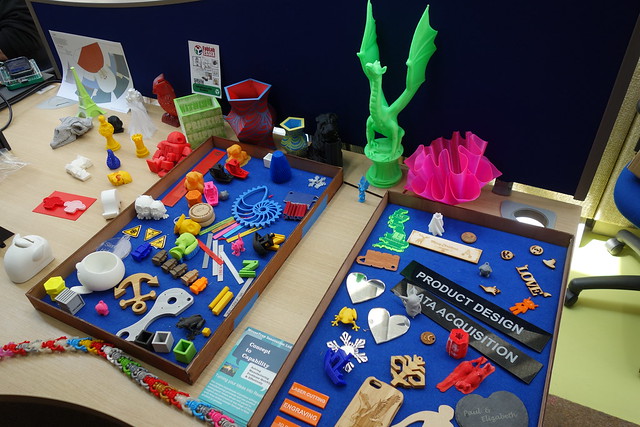
FabLab Essex had lots of interesting 3D printed / laser cut examples on display.
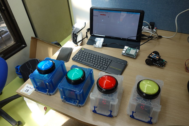
Barry Byford with his cool microbit powered big button game on show.
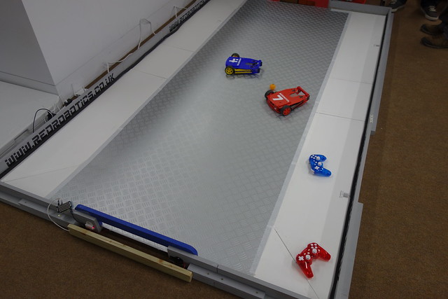
Neil Lambeth with his awesome football robots.
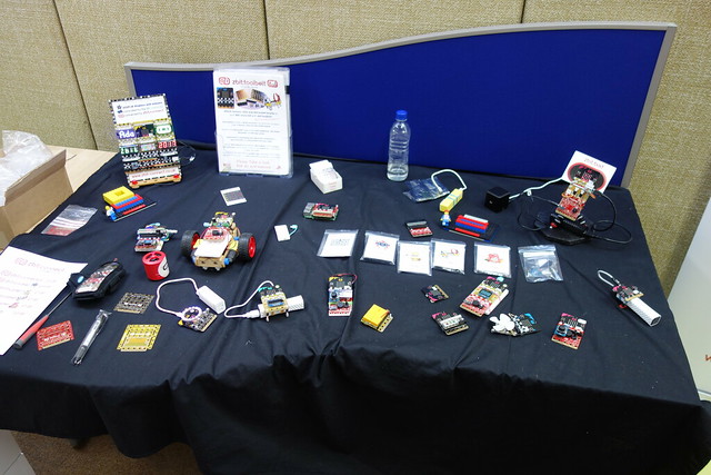
Nevil Hunt with his zbit:connect projects on show.
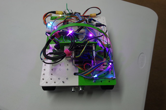
A nice prize winning PiWars robot.
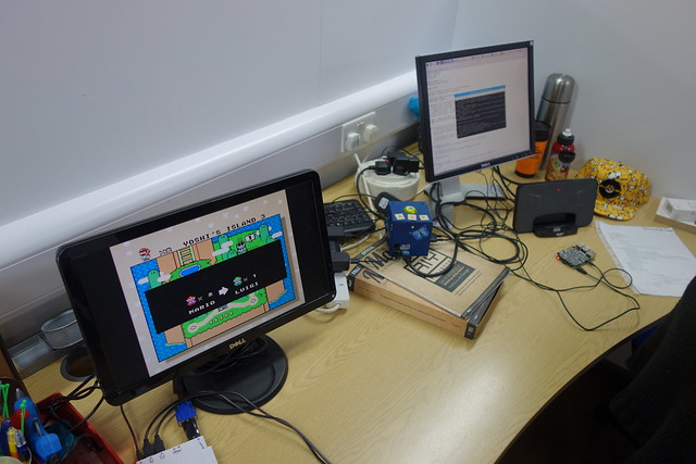
Some rather cool Raspberry Pi projects on show.
Some more pictures can be found on my Flickr page.
Hobby electronics, Raspberry Pi, micro:bit, retro computing and vintage test equipment.
Saturday, 20 May 2017
Wednesday, 3 May 2017
14th Egham Raspberry Jam
On Sunday 30th April I travelled down Egham to attend the 14th Egham Raspberry Jam, it's my third time I have attended this particular jam. It was held at the Gartner UK HQ offices, which was easy to find and had plenty of parking. There were plenty of cool show and tell projects to look at, but no workshops or talks.
I took some awesome Boldport club projects and a colour mixing Raspberry Pi project along. I spent most of my time talking to people about my projects, however I did manage to have a look at the other projects on show.
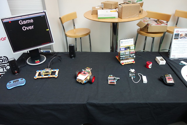
Some of my projects on display.
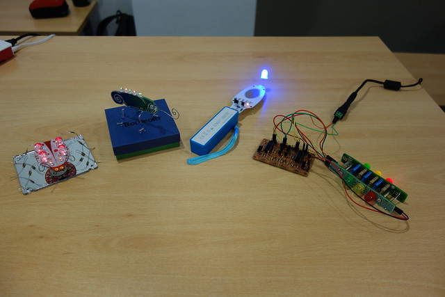
A collection of awesome Boldport Club projects.
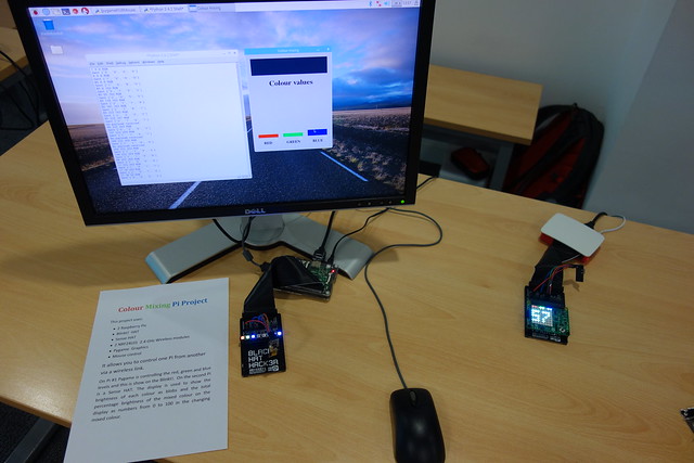
My colour mixing Raspberry Pi project.
A nice collection of Zbit boards from Nevil Hunt.
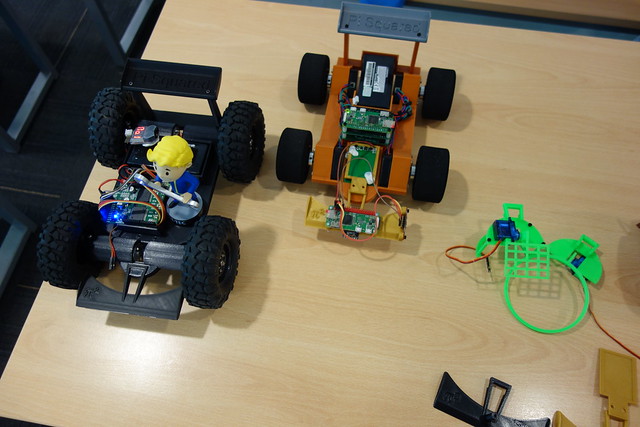
A couple of Raspberry Pi powered robots.
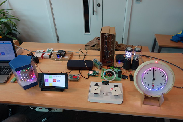
A nice collection of projects made by David Sweeney.
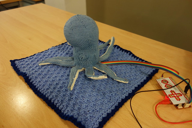
Musical Octopus, using the awesome Makey Makey board.
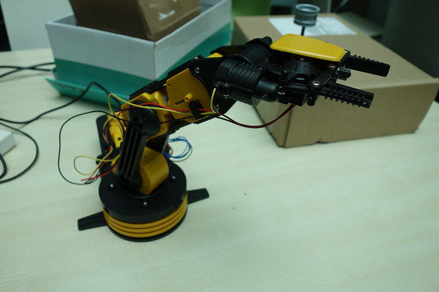
Matt Sendorek's Raspberry Pi controlled Maplin robot arm.
Some more pictures can be found on my Flickr Page.
Tuesday, 2 May 2017
Commodore 1541 Disk Drive Repair
I recently acquired a classic Commodore 1541 disk drive. It was in good condition, powered on and came with the original transit card (sometimes called a ”head vibration protector”).
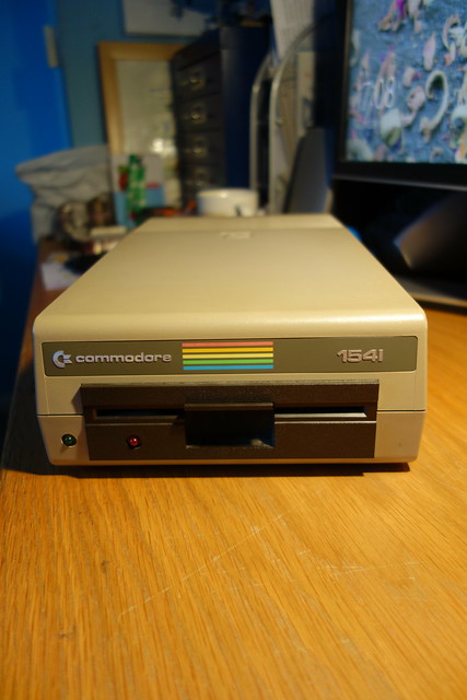
When it arrived I opened it up to have a peek inside. There is a large PCB which contains a MOS 6502 microprocessor, 2x MOS 6522 Versatile Interface Adapter (VIA) IC’s, rom, ram and various glue logic. I gave it a quick clean and powered the drive on, no magic smoke escaped. The drive powered up normally but the spindle motor didn’t appear to be running hmmmm.
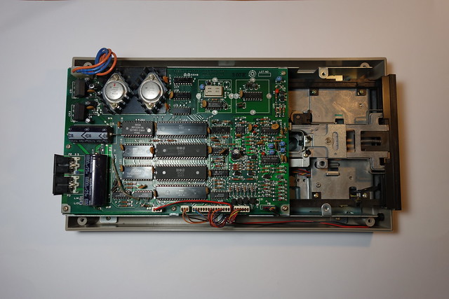
Luckily there is plenty of technical information about these drives available on the web. Here are a couple of useful websites.
Bo Zimmerman's Commodore 1541 disk drive information
Ray Carlsen's Commodore 1541 disk drive repair information
I started checking voltages, the +5v supply was ok but the +12v supply was missing. This could be caused by an overload due to a shorted tantalum capacitor (C15) which sits across the+ 12V rail. I replaced the capacitor but this made no difference, it would appear that the +12v regulator (LM340KC-12) was dead.
These voltage regulators come in a TO-3 style package but I didn’t have any of these in my component stocks, so I had a quick hunt on eBay for some replacements. A few days later the voltage regulators turned up so I set about replacing the faulty one. After I fitted the new voltage regulator I checked the voltage rails, both the +5v and +12v were now present.
I powered the drive on, the green LED came on and stayed on, the red activity LED came on and the spindle motor ran for about two seconds then the red LED went out and the spindle motor stopped. Good news I could now test the drive.
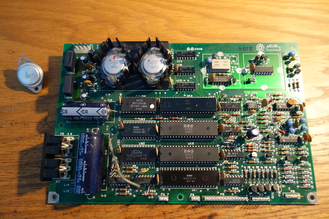
Next step testing the drive:
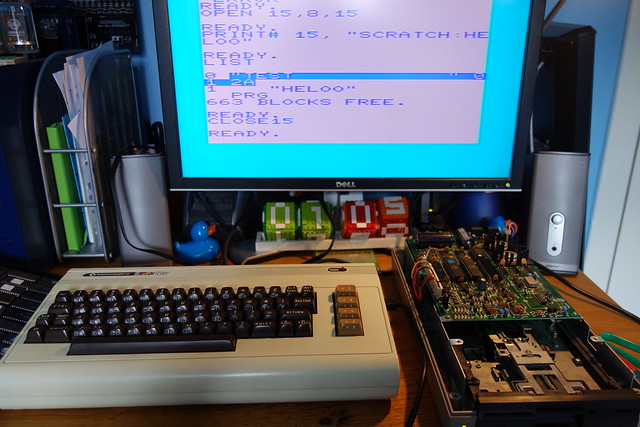
I hooked up the disk drive to my VIC20 and gave it a whirl, well that proved to be fruitless. I tried to format a disk which started well, the red activity LED came on, the drive spindle motor was spinning and the head started to move across the disk. The format failed as the head stopped moving across the disk, the red activity LED started to flash (which indicates an error) but there were no error messages on the screen.
Format failures can be caused by a write protect (disk tab on), drive door open, bad disk, bad or clogged head, or bad chips in the drive. I tried cleaning the head with some alcohol and a cotton tip and then tried again. Well that didn’t work, so I took a punt and swapped out the one of the 6522 VIA chips (UC2) which deals with the motor control logic. Success the drive would now format a disk and read OK.
When it arrived I opened it up to have a peek inside. There is a large PCB which contains a MOS 6502 microprocessor, 2x MOS 6522 Versatile Interface Adapter (VIA) IC’s, rom, ram and various glue logic. I gave it a quick clean and powered the drive on, no magic smoke escaped. The drive powered up normally but the spindle motor didn’t appear to be running hmmmm.
Luckily there is plenty of technical information about these drives available on the web. Here are a couple of useful websites.
Bo Zimmerman's Commodore 1541 disk drive information
Ray Carlsen's Commodore 1541 disk drive repair information
I started checking voltages, the +5v supply was ok but the +12v supply was missing. This could be caused by an overload due to a shorted tantalum capacitor (C15) which sits across the
These voltage regulators come in a TO-3 style package but I didn’t have any of these in my component stocks, so I had a quick hunt on eBay for some replacements. A few days later the voltage regulators turned up so I set about replacing the faulty one. After I fitted the new voltage regulator I checked the voltage rails, both the +5v and +12v were now present.
I powered the drive on, the green LED came on and stayed on, the red activity LED came on and the spindle motor ran for about two seconds then the red LED went out and the spindle motor stopped. Good news I could now test the drive.
Next step testing the drive:
I hooked up the disk drive to my VIC20 and gave it a whirl, well that proved to be fruitless. I tried to format a disk which started well, the red activity LED came on, the drive spindle motor was spinning and the head started to move across the disk. The format failed as the head stopped moving across the disk, the red activity LED started to flash (which indicates an error) but there were no error messages on the screen.
Format failures can be caused by a write protect (disk tab on), drive door open, bad disk, bad or clogged head, or bad chips in the drive. I tried cleaning the head with some alcohol and a cotton tip and then tried again. Well that didn’t work, so I took a punt and swapped out the one of the 6522 VIA chips (UC2) which deals with the motor control logic. Success the drive would now format a disk and read OK.
Subscribe to:
Posts (Atom)