Sunday, 17 December 2017

6502 Badge


I recently built a rather nice 6502 Anniversary Computer Badge which was designed to celebrate the 40th Birthday of the Apple II, Commodore PET, and Atari VCS.

Get your own here 6502 40th Anniversary Badge 


Description:


  • A 65C02 microprocessor, running at 2 MHz
  • 2K RAM (expandable to 16K or 32K), with battery backup
  • 16K EPROM (expandable to 32K), with floating-point BASIC and 6502 machine-level monitor
  • Two 8-bit output latches
  • 7-digit 7-segment LED display, plus annunciators
  • Software-driven 9600 baud TTL serial I/O port

I made following mods to the build:


  • I socketed all of the chips using nice turned pin IC sockets, except the 2K RAM which is soldered directly to the PCB.

6502 Badge bare PCB


6502 badge, nearly completed 


 6502 badge, with almost everything socketed.


Friday, 15 December 2017

Further 8-bit Adventures

I recently was experimenting with the user port on my VIC 20 while trying not to blow it up.   The VIC20 has various Input/output ports one of which is the user port (really, just the exposed edge of the printed circuit board) on the back of the computer. 

The user port is connected to one of the VIC20’s two 6522 Versatile Interface Adapter (VIA) chips.In my experiments I am using the eight lines which can be set as inputs or outputs.

The first hurdle was figuring out how to connect my projects to the user port, luckily suitable connectors are still available. I got mine from the brilliant The Future was 8 Bit web Shoppe.   

I made up a suitable cable using some ribbon cable and the other ends of the wires are plugged into a breadboard.

Here’s a picture of the connector after I soldered some ribbon cable to it.


I found the binary light display project in the Usborne Practical Things Do with a Microcomputer book and thought I would have a go. 

I simply connected a LED to each of the 8 I/O lines. The cathodes are connected via 220Ω resistor to the user port’s ground.  Some of the classic Usborne 1980s computer books are freely available to download as PDFs from here.


The software is fairly simple.  The chip controlling the user port is a 6522 Versatile Interface Adapter (VIA).  From BASIC, you can PEEK it to read an INPUT or POKE it to set an OUTPUT.

For example:
10 POKE 37138, 255
20 FOR I = 0 TO 255
30 POKE 37136, I
40 FOR J = 1 TO 150
50 NEXT J
60 NEXT I
70 GOTO 20

Line 10 sets the Data Direction Register (DDR) which controls whether that line will be an input or an output and line 30 turns the individual lines on and off.  Each LED lights up in a pattern of 0s and 1s for each binary number from 0 to 255.

Having made some LEDs flash I wondered if a seven segment display could be made to count from 0 to 9.  I took my Seven Segments of PI board which is designed to work with a Raspberry Pi and connected it to the user port.    

I found an example in a book called Practical Interfacing Projects with the Commodore Computers.


I had to modify the code slightly as the circuity is different from the example given.

10 POKE 37138,255: A=37136
20 POKE A,40:GOSUB500
30 POKE A,157:GOSUB500
40 POKE A,185:GOSUB500
50 POKE A,58:GOSUB500
60 POKE A,179:GOSUB500
70 POKE A,183:GOSUB500
80 POKE A,41:GOSUB500
90 POKE A,191:GOSUB500
100 POKE A,59:GOSUB500
110 POKE A,175:GOSUB500
120 GOTO20
500 FOR I=1 TO 1000:NEXT:RETURN

Saturday, 20 May 2017

Southend Raspberry Jam 11

Today I travelled down to Southend on Sea to attend my first Southend Raspberry Jam, unfortunately this involved leaving home at some unreasonable hour on a Saturday.  The Jam was held at the The Hive Enterprise Centre (formerly the old central library).   

There were plenty of cool show and tell projects to look at,  some workshops and interesting talks.

I took some 
I took the Mega:bit and Micro Simon along I spent most of my time talking to people about my projects, however I did manage to have a look at the other projects on show.

My projects on display.

DSC03351

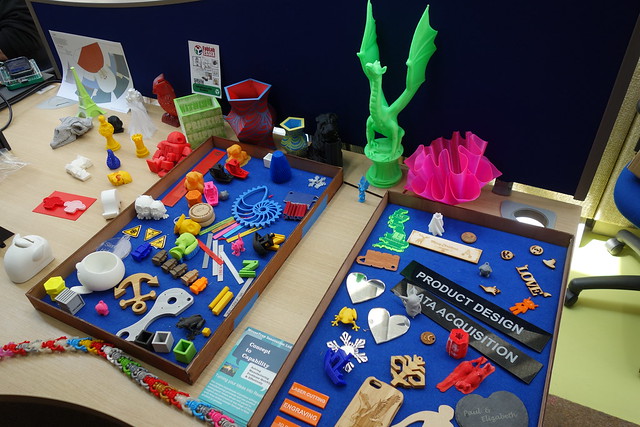
FabLab Essex had lots of interesting 3D printed / laser cut examples on display.

DSC03353

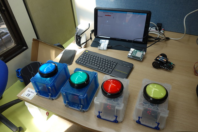
Barry Byford with his cool microbit powered big button game on show.

DSC03356

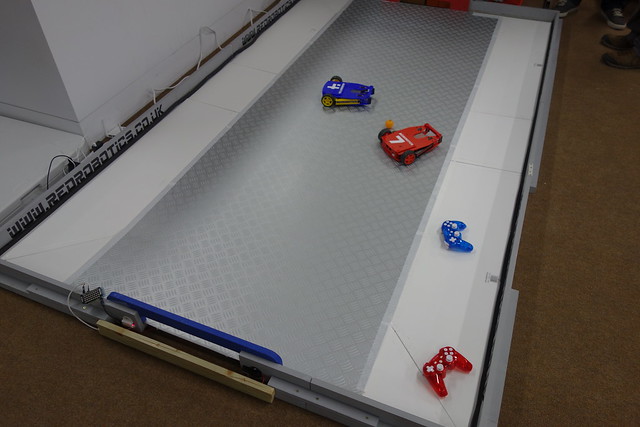
Neil Lambeth with his awesome football robots.

DSC03361

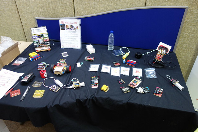
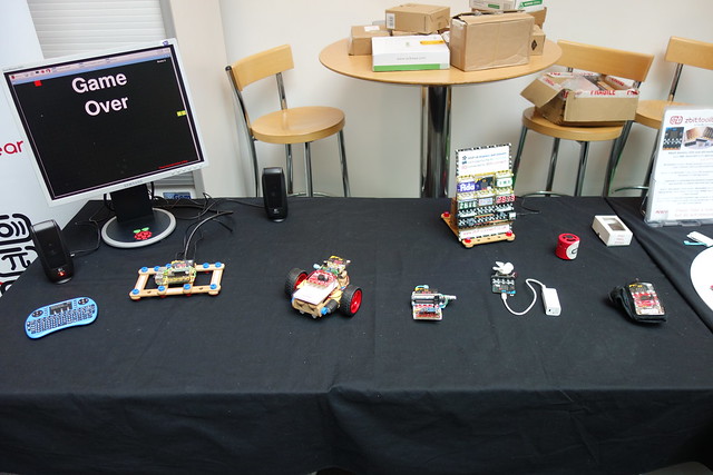
Nevil Hunt with his zbit:connect projects on show. 

DSC03371

A nice prize winning PiWars robot.

DSC03370

Some rather cool Raspberry Pi projects on show.

DSC03367

Some more pictures can be found on my Flickr page.   

Wednesday, 3 May 2017

14th Egham Raspberry Jam

On Sunday 30th April I travelled down Egham to attend the 14th Egham Raspberry Jam, it's my third time I have attended this particular jam. It was held at the Gartner UK HQ offices, which was easy to find and had plenty of parking. There were plenty of cool show and tell projects to look at, but no workshops or talks.

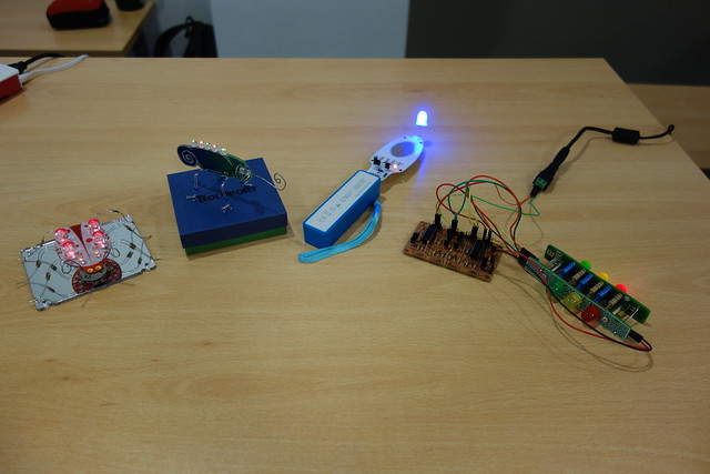
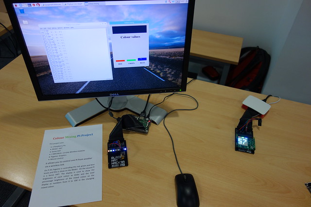
I took some awesome Boldport club projects and a colour mixing Raspberry Pi project along.  I spent most of my time talking to people about my projects, however I did manage to have a look at the other projects on show.

Some of my projects on display.

A collection of awesome Boldport Club projects.   

DSC03179

My colour mixing Raspberry Pi project.

DSC03181

A nice collection of Zbit boards from Nevil Hunt.

DSC03182

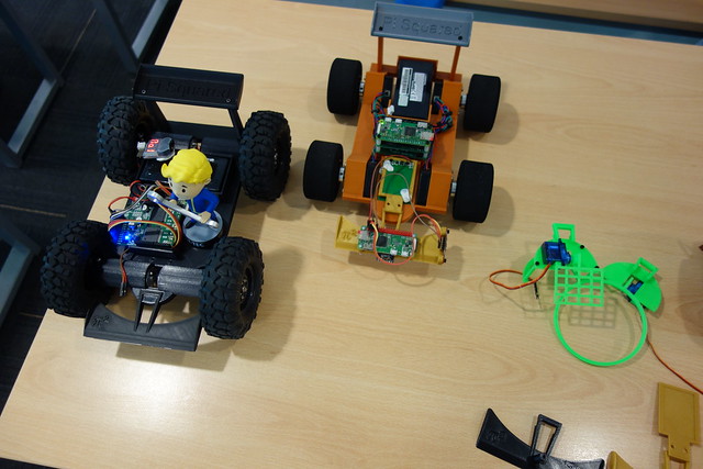
A couple of Raspberry Pi powered robots.

DSC03185

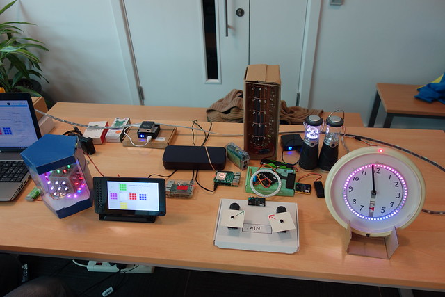
A nice collection of projects made by David Sweeney.

DSC03189

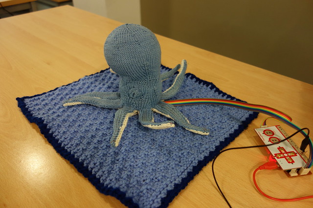
 Musical Octopus, using the awesome Makey Makey board.

DSC03191

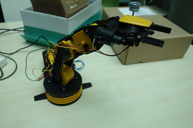
Matt Sendorek's Raspberry Pi controlled Maplin robot arm.


DSC03192

Some more pictures can be found on my Flickr Page.

Tuesday, 2 May 2017

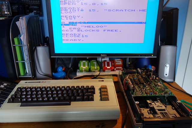
Commodore 1541 Disk Drive Repair

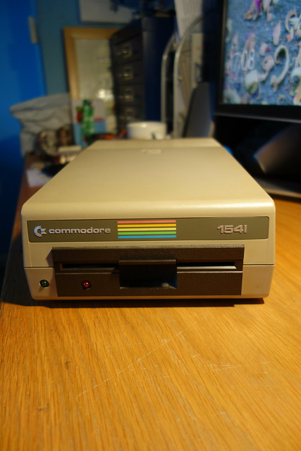
I recently acquired a classic Commodore 1541 disk drive.  It was in good condition, powered on and came with the original transit card (sometimes called a ”head vibration protector”).   


DSC02640

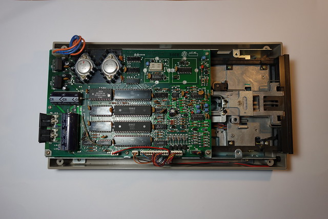
When it arrived I opened it up to have a peek inside. There is a large PCB which contains a MOS 6502 microprocessor, 2x MOS 6522 Versatile Interface Adapter (VIA) IC’s, rom, ram and various glue logic. I gave it a quick clean and powered the drive on, no magic smoke escaped. The drive powered up normally but the spindle motor didn’t appear to be running hmmmm.

DSC02641


Luckily there is plenty of technical information about these drives available on the web. Here are a couple of useful websites.

Bo Zimmerman's Commodore 1541 disk drive information

Ray Carlsen's Commodore 1541 disk drive repair information

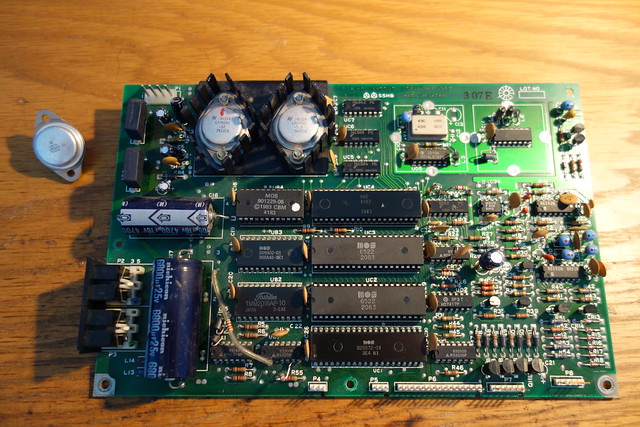
I started checking voltages, the +5v supply was ok but the +12v supply was missing. This could be caused by an overload due to a shorted tantalum capacitor (C15) which sits across the +12V rail. I replaced the capacitor but this made no difference, it would appear that the +12v regulator (LM340KC-12) was dead.

These voltage regulators come in a TO-3 style package but I didn’t have any of these in my component stocks, so I had a quick hunt on eBay for some replacements.  A few days later the voltage regulators turned up so I set about replacing the faulty one. After I fitted the new voltage regulator I checked the voltage rails, both the +5v and +12v were now present.  

I powered the drive on, the green LED came on and stayed on, the red activity LED came on and the spindle motor ran for about two seconds then the red LED went out and the spindle motor stopped.  Good news I could now test the drive.


DSC03173


Next step testing the drive:

I hooked up the disk drive to my VIC20 and gave it a whirl, well that proved to be fruitless.  I tried to format a disk which started well, the red activity LED came on, the drive spindle motor was spinning and the head started to move across the disk. The format failed as the head stopped moving across the disk, the red activity LED started to flash (which indicates an error) but there were no error messages on the screen.   

Format failures can be caused by a write protect (disk tab on), drive door open, bad disk, bad or clogged head, or bad chips in the drive.  I tried cleaning the head with some alcohol and a cotton tip and then tried again.  Well that didn’t work, so I took a punt and swapped out the one of the  6522 VIA chips (UC2) which deals with the motor control logic.   Success the drive would now format a disk and read OK.

DSC03198


Tuesday, 28 February 2017

Retro LED Displays

I recently brought some of these rather nice Texas Instruments TIL311 hexadecimal displays from eBay, they are really small but beautiful.  This got me thinking, could I connect one of these displays to a micro:bit.  

TIL311 Displays


Looking at the TIL311 datasheet, I came across the first hurdle.  The TIL311 is a TTL device and needs 5v to work but the micro:bit runs at 3.3v so I needed a level shifter / buffer IC to interface between them, you could probably get away without a level shifter but I aired on the safe side. I chose the 74HCT244N but I used a 74HC244N as this is what I had in stock.


The TIL311 has a 4-bit data input A,B,C,D  which I connected to pins 0,1,2 & 8 on the micro:bit via a 74HCT244N and used separate 5v supply for the display.  To figure out how to display 0 to 9 I looked at the truth table for a 7490 decade counter and then replicated this in Python by turning the outputs on and off.


The finished project


My rather noddy Python code, I'm sure there must be a neater way of doing this.


  1. from microbit import *
  2. pins = [pin0, pin1, pin2, pin8]
  3. while True:
  4.     0#
  5.     pin0.write_digital(0)
  6.     pin1.write_digital(0)
  7.     pin2.write_digital(0)
  8.     pin8.write_digital(0)
  9.     1#
  10.     pin0.write_digital(1)
  11.     pin1.write_digital(0)
  12.     pin2.write_digital(0)
  13.     pin8.write_digital(0)
  14.     sleep(500)
  15.     2#
  16.     pin0.write_digital(0)
  17.     pin1.write_digital(1)
  18.     pin2.write_digital(0)
  19.     pin8.write_digital(0)
  20.     sleep(500)
  21.     3#
  22.     pin0.write_digital(1)
  23.     pin1.write_digital(1)
  24.     pin2.write_digital(0)
  25.     pin8.write_digital(0)
  26.     sleep(500)
  27.     4#
  28.     pin0.write_digital(0)
  29.     pin1.write_digital(0)
  30.     pin2.write_digital(1)
  31.     pin8.write_digital(0)
  32.     sleep(500)
  33.     5#
  34.     pin0.write_digital(1)
  35.     pin1.write_digital(0)
  36.     pin2.write_digital(1)
  37.     pin8.write_digital(0)
  38.     sleep(500)
  39.     6#
  40.     pin0.write_digital(0)
  41.     pin1.write_digital(1)
  42.     pin2.write_digital(1)
  43.     pin8.write_digital(0)
  44.     sleep(500)
  45.     7#
  46.     pin0.write_digital(1)
  47.     pin1.write_digital(1)
  48.     pin2.write_digital(1)
  49.     pin8.write_digital(0)
  50.     sleep(500)
  51.     8#
  52.     pin0.write_digital(0)
  53.     pin1.write_digital(0)
  54.     pin2.write_digital(0)
  55.     pin8.write_digital(1)
  56.     sleep(500)
  57.     9#
  58.     pin0.write_digital(1)
  59.     pin1.write_digital(0)
  60.     pin2.write_digital(0)
  61.     pin8.write_digital(1)
  62.     sleep(500)

Sunday, 26 February 2017

Telequipment D65

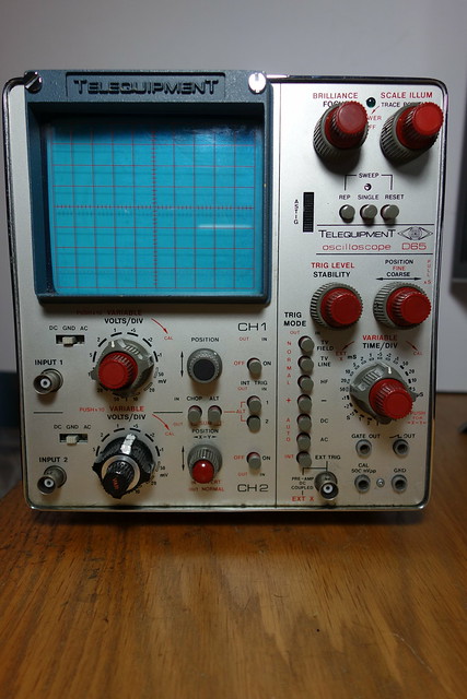
Some time ago I acquired an old 1976 vintage Telequipment D65 - 15MHz, all solid state dual-trace scope.  Unfortunately it had a couple of faults which is why it was being thrown away.

Telequipment D65

The scope basically worked but.
  1. It wouldn't turn on as the scale illumination / power switch knob was cracked and therefore kept slipping
  2. The trigger was intermittent, when powered on the triggered sweep may decide to a) start halfway across the screen, b) in the correct position and then fade or c) work as advertised.
Well the first thing I did was fix the broken knob, nothing a bit of superglue didn’t solve. This was only a temporary fix until I obtained a replacement second hand knob.  Now I could move onto fixing the annoying intermittent trigger fault. 

After a bit of digging around on the net I stumbled across this post on the UK Vintage Radio Repair and Restoration forum. Somebody else was having the same issue which could be fixed by tapping the trigger knob or the side of the case for that matter. 

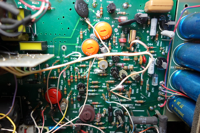
Trigger, Timebase X amp & blanking PCB
Troublesome PCB


The fault was on the trigger, time base x-amp and blanking PCB.  It would seem that these scopes use doubled sided PCB's with naff though hole links which go bad with age. I re-flowed the solder on all the little links and this fixed the problem. 

Overall I'm pleased with this little scope which weighs 11.5Kg, it has made a  great addition to the workshop.  I should recap the power supply board at some stage.

Some more pictures of this scope can be found on my Flickr page.